CIV1O2: Building a Bridge Using Matboard
Aarya Shah
1/26/20255 min read
In my first semester, I had the opportunity to take “CIV 102 — Structures and Materials: An Introduction to Engineering Design” where we applied our knowledge of beams, bending moments, shear forces and axial loads to design a ‘small-scale box-girder beam bridge’ using an 813 mm × 1016 mm × 1.27 mm, and 60mL of contact cement. The bridge would be tested based on strength-to-weight ratio, and if it can withstand a dynamic load. This process allowed us to integrate the engineering design cycle we learnt in Praxis to frame, diverge, converge and represent an ideal design.
This opportunity allowed me to bridge the difference between theory and application, while proving the accuracy of simple equations and formulas in large-scale constructions.
1. Framing our Opportunity
Our scope was pre-identified by our requirements framework. The assignment detailed that:
The bridge shall be between 1250mm-1270mm in length
The bridge shall have a track height of no more than 200mm, and the distance from the track (the top of the bridge) to the supports shall be a multiple of 20mm.
The bridge deck shall not be more than 100mm in width
The bridge shall have a flat 50mm surface on either edge for the supports.
We were provided with a base case with train dimensions shown below:
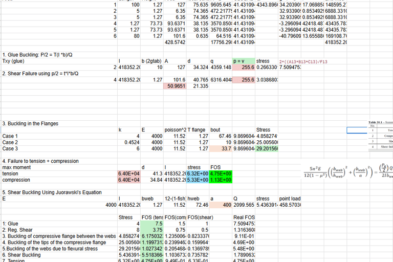
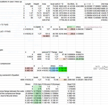
Our group developed a MATLAB code to create a shear force and bending moment envelope that assessed the maximum bending moment and shear force, the train’s location when that maximum value would be reached, and its corresponding shear and bending moments. Using a provided cross-section, we used Google Sheets and hand calculations to find the following Tensile and Shear Stresses the bridge must withstand and their corresponding factors of safety:
Tensile Failure of Bridge Walls
Compressive Failure of Bridge Walls
Shear Failure of Bridge Walls
Shear Failure of Reinforcement (contact cement)
Thin Plate Buckling of the compressive flange between webs
Thin Plate Buckling of the tips of the compressive flanges
Thin Plate Buckling of the webs due to flexural stresses
Shear buckling of the webs
The calculations for our preliminary design are below, providing us with FOS values above 1 for each failure mode, justifying this to be a satisfactory starting point.
However, we had to diverge and create multiple iterations to our design to increase the strength and build a bridge that accurately aligns with our requirement framework.
2. Diverging to Find A Better Bridge Design
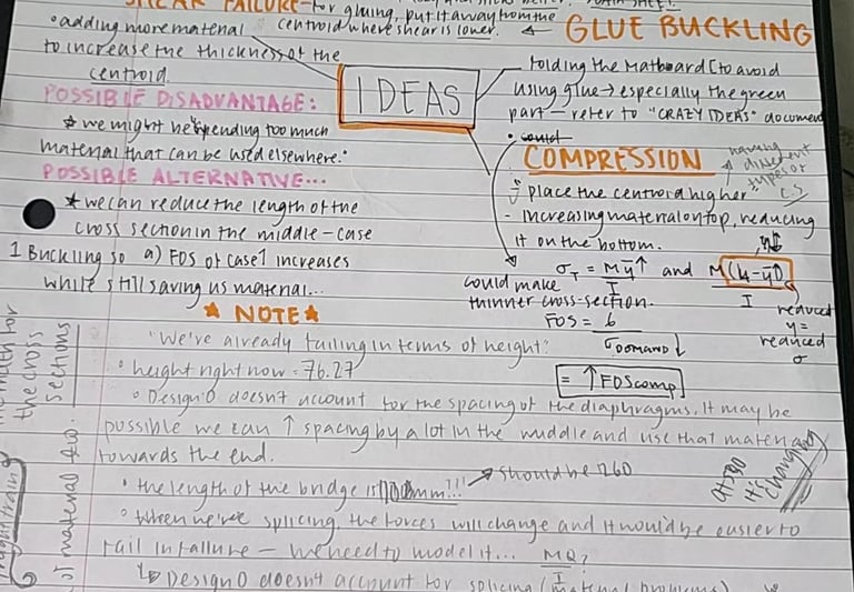
The biggest limitation in the preliminary design draft we were provided was that it did not meet the requirements framework in length, width and height. We first brainstormed a list of possible limitations and ideas we had for our design to informally explore the majority of the design space.
In regards to cross-sections, cylinder cross-sections are deemed the most effective because they have an equal moment of inertia throughout and are very uniform. However, if the cross-section is not mastered, it can be disastrous. Hence, we eliminated the idea of having a uniform hollow cylinder cross-section but decided to opt for a uniform cross-section.
We also realized that many cross-sections require a lot of material. While this is necessary at the edges of the bridge where shear force and bending moments are highest and since it is near support, implementing large cross-sections might ‘over-design’ the bridge and create a waste of material. Consequently, we decided to have three types of cross-sections depending on various bridge locations.
The same logic was used when deciding the placements of our diaphragms.
Something that seemed risky was choosing to implement two shear splice connections rather than one. The rationale behind this was to maintain the symmetry of the bridge, and because it would have a smaller distance and force to transfer. Our splice connections were covered with a piece of Matboard, almost like a bandaid, and the splice connection would have to effectively transfer all the internal forces from one side to the other without fail. If we placed the splice connections in an area with less shear force and bending moment, as well as it having a smaller distance from the support, it will be less vulnerable to sudden failure.
3. Converging To Our Best Design Decisions
Based on our scarce resources, and time, we realized it would be impossible to accommodate all ideas, and resorted to ideas that we believed would optimize the design while being feasible. Since the provided MATboard and the preliminary design did not meet the length constraint, we implemented shear splice connections, increasing the bridge’s stress. We created a taller cross-section to fit with our requirements. Constant iterations taught me that it is difficult to get the perfect design on the first try, as it involves critical analysis, testing, analyzing and reflecting on your results.
To test our ideas, we altered the Google Sheets to check the impact it would have on the ‘Real FOS’ values and used CAD software like Fusion 360 to highlight our ideas when constructing.
Our final design decisions are noted below:
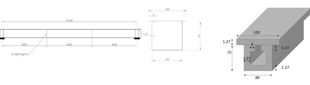
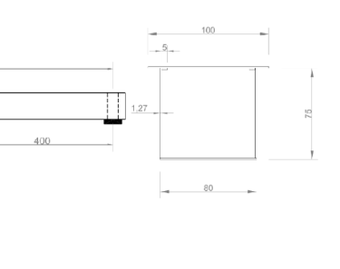
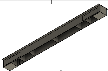
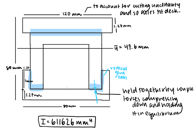
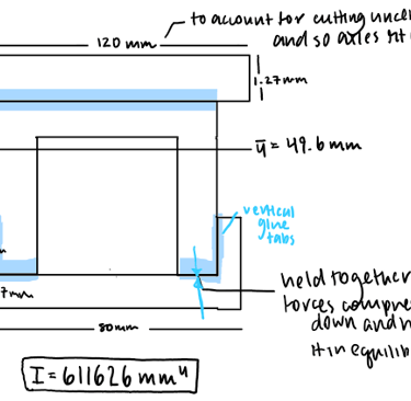
Having a uniform ‘inverted box’ cross-section (see below):
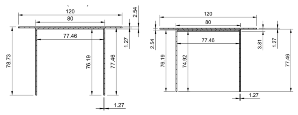
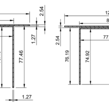
Implementing three different cross-section designs throughout the bridge based on shear force and bending moments at particular locations (see below for Cross Sections 2 and 3)
Having varying distances between diaphragms to account for areas with higher or lower shear/bending moments.
Using shear splice connections instead of lapping techniques
Using 10mm glue tabs although the length of the cross-sections are more than that
Adding a small support between the web of cross-section 3 to lower thin plate buckling
Changing the dimensions of our bridge to a length of 1260mm, height 0f 80mm and width of 120mm.
4. Results
From our final iterations, our bridge was predicted to withstand 460N of load and fail due to thin plate buckling of the compressive flanges between the webs of cross-section 2. In between the designing and constructing process, we noted that some considerations such as adding less glue might not be the best approach after all because we do not know whether the glue will reach its maximum strength of 2MPa, or if we make a mistake with folding the Matboard or gluing.
We hypothesized that the bridge might be subjected to fail earlier because the cross sections do not behave as rigid bodies. While equations provide an approximation when the bridge experiences a load, it’s likely to create a ‘sinusoidal effect’ on the track of the bridge, and the cross sections are likely to bend if they’re too thin.